
Radar installation
Overview
This spring we purchased a new Garmin Fantom 18 radar for Sundog. For the installation location I read many pages of forum posts debating the topic of mast vs stern pole/arch mounting. I came to the personal conclusion that there seemed to be no one clear solid choice for the location. There seemed to be equal number of opinions as to which was best. I finally decided to go for the mast mount choice as I preferred it for the radar being up higher for possible range benefits and radiation being away for the crew. I choose was the ScanStrut LMM-1 Self Levelling mast mount since I did want the benefits of the swing when heeled over while sailing.
Running power and data connections
This is one of the drawbacks of the mast mount is that I would need to run the power and data connection cables to mast base. The power cable would be “relatively” simple as it would be run from the chart table to the mast base. The data cable would be a harder task as this needed to be run from the chart plotter at the helm all the way to the mast base.
Power to the mast base
I started the power cable run as the first task. Looking at how other cables were run I was able to see an existing fiberglass fastened conduit that went from the back of where my battery switches are (the forward seat on the starboard side). I could then see being able to run the power cable behind the game table and other seat to the back of the battery compartment and then to below the chart table. I was able to use a fish tape to get the cable from the mast base through to seat and then over to the battery compartment. That was the difficult portion. Then rest was very simple for getting the cable up to the electrical panel and completing the wiring. I used the AUX 2 position on the electrical panel as I made this available by moving the boat monitor USB power outlet to be permanently on and directly connected to the power bus bar in the panel.
Pictures below are for the power cable routing.
-

- From bilge toward mast step
-

- Into the conduit beneath floor
-

- Out of conduit into spot behind seats where battery switches are
-

- Back into conduit along the hull
-

- Behind the battery compartment
The pictures below are electrical panel connections. As you can see I had cut the power fuse holder from the supplied Garmin power cable and put that on the end of the power cable where it would connect to the panel switch. The fuse for the radar is 7.5Amp and the panel switch is a 10Amp fuse.
-

- Radar power breaker connection
-

- Radar power ground connection
At the mast base I used an electrical junction box and had epoxied a piece of wood inside to put a terminal block on. I used this for my mast step power connection as again, we take the mast off in the fall and we need to be able connect/disconnect our radar power supply.
-

- Power cable with grommet, securing nut and cable cover.
-

- Power cable getting eye terminal crimped and shrink wrapped on.
-

- Final view of the power connection ready for mast cable.
Data cable
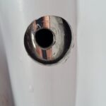
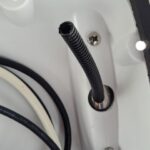
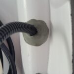
The data cable run was the second task to be done. This involved cutting another hole into the pedestal guard as there was no way I could fit the data cable down the hold that I had used for the NMEA2K, power and radio microphone cable from my previous work. I needed to carefully drill the hole since that side of the pedestal had the cables for the older Raymarine Seatalk connections for my other instruments. After I drilled the hole I then used a Dremel to round and smooth the hole and enlarge it sufficiently such that I could run the data cable. For protection I inserted a piece of split loom cable cover into the hole that the data cable would be run down. Then around this for protecting against water intrusion I placed bits of butyl tape pressed down around it.
-

- Starting to drill pedestal guard
-
- Hole sized for cable
-
- With cable guard
-
- Addition of buytl tape
As the Garmin cables come with the connectors crimped on and the large connectors, I had to cut the end to be able to feed that down the guard and into the aft cabin. The cable was then run to the starboard locker, into one of my newer conduits (see Chart plotter installation) and through to below the chart table. From there, the cable goes through the bilge area over the base of the mast.
-

- Down from helm via pedestal
-

- Out into stern locker to get into the conduit
-

- Out of the conduit inside aft cabin closet
-

- Under the floor to the mast step
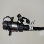
I then crimped on the end of the Garmin data cable for attaching to the connector. I am using the connector as we generally take down the mast every fall so making a fast and easy connection is what I wanted. The additional benefit is that these should be watertight secure connections. And finally I connected the data cable to the back of the chart plotter and closed up the Navpod.
-
- Mast step data connection coupler
-
- Data cable connected to the chartplotter
Mast mount installation
Supporting the mast during installation
This is probably the task that I have worried the most over doing. Sure I was concerned when I had done the exterior hole in the boat when done the solar panel installation but this seemed more of a concern because if I screwed up and ruined the mast somehow that would be a very expensive mistake. So with Sharron’s help we started the mast install by first placing the mast with front up and securing it vertically with some wood blocks screwed into the mast rack.
-

- Mast supports
Installing the mount
The mount is attached by four feet that have holes for fastening with pop-rivets. We first put tape down so that we could position the mount on the mast and mark all the drill holes. We then drilled all the holes for the feet and removed the tape.
The next step was to actually perform the pop-rivet of the feet. I had a little trouble getting the right action/steps to do for the rivet gun to work. After getting them all done I was relieved that they were all done cleanly without any issues with the final product.
-
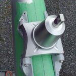
- Placement and ready for drilling
-
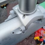
- Pop-rivet work done!
-

- Working under COVID-19 protocols
Drilling hole for cable entry and pulling the cables.
Yes the big hole for the power and data cables. I wanted to make sure this was the ‘minimum’ size hole that I would need to the two cables to get down the mast. I again put tape on the mast for marking where I would drill. After a successful base hole being created I used a Dremel tool again for increasing the hole size a bit and for smoothing out edges to reduce and possible cut/damage for the cables.
With the hole now ready, it was now time to get the cables down the mast from the mount location. I must have been way too optimistic on the conduit space as I thought I could simply ‘push’ the cables down. Well that did not get us too far. I then had to use a fish tape pushed up the mast from the base. We then had a messenger line out of the hole to be able to use for pulling down the power and data cables. This was a much easier job with the line and we soon had the cables out the mast base. The old trouble I realized after is that I had taped the cables together in several spots at the start of the cable. I had not properly evened out the cables so we had a bit of an extra of power cable at the top. I was worried about this but decided not to pull the cables back out. We ended up securing the extra bit at the top and I think this will be ok.
-

- Power and data cable hole
-

- Finishing the hole edges
-

- Starting to pull the cables
-

- Success! Cables out mast base.
Mounting radar
With the mount and the cables ready it was on to putting the radar onto the mount. We first put the swing arm onto the mount, secured with the thumb screw and adjusted for what we hope is the right angle of the radar. The power and data cables were connected to the radar and it was then put onto the swing arm.
There is a security line from the radar to the mast that needed to be fastened to the mast. This is the second slip up that I made when I messed up one of the pop rivets on the little bracket. Of course the supplied package of parts does not include any spares. With no spares of my own for this size we had to make a quick trip over to the marine store to buy a few rivets. I bought extras so that if I do another job I would now have spares. Back at the mast rack, I was able to put the final rivet in. The final step of the radar mounting was to secure the cables to the swing arm.
-

- Radar secured on the swing arm.
-

- Final rivet! Security cable fastened to the mast.
-

- Cables secured to the arm. Note oops with the extra loop of one cable.
-

- Other view of the cables secured on the arm
Finishing up on the install on the mast
The final touch was putting the marine sealant (3M 5200) around the cables and mast entry hole to prevent water getting in.
-

- Final touch. Sealing up the cable hole.
Radar Power up and test
With the COVID-19 state of emergency and lock downs, we could not go back to the boat after it was launch and the mast was put in by the great staff at Collins Bay Marina. Once we were finally able to go back to the marina. I finished up the power and data cables from the mast by putting the eye terminals on the power cable and crimping the data connection end on.
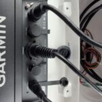
I then connected the mast cables to the connections I had prepared and we were all set for testing. I powered up and went to the chart plotter to confirm that the radar was visible on the communications. I was then able to look through the chart plotter menus and access the radar options for turning the transmit on and seeing it sweep and display data. It was not until our first sail that we really got to start to work with the radar and look at what it could tell us.
-

- Power and data connections made
-

- Success! The radar is visible on the chartplotter.
-

- Initial Tx enable of the radar.
-

- Radar with chart overlay as we do our first sail out of the bay.

Recent Comments